
LEARN: Solid-State LCD Shutter Project
What is it? How does it work? Why is it useful?

Introduction
This article outlines a type of solid-state (no moving parts) shutter that can be used for camera lenses or light sources, to precisely control the amount of time that light can pass through. I’ll explain where the idea came from, how it works in practice, how I fitted one into an old box Brownie camera, and some tips and tricks in case you wanted to try to make one yourself.
Origin of project
Some years ago now, I became interested in a device I had seen online that allowed welders to see what they were working on, but that automatically darkened to a safe level whenever a welding arc was struck. I realised that these must operate extremely quickly, be entirely solid-state and most likely operated using a sort of liquid crystal element.
I found some cheap automatic welding glasses on eBay and set about trying to discover their secrets
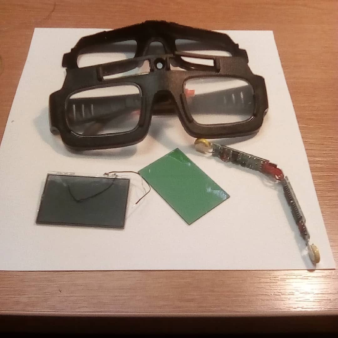
They were disturbingly simple to dismantle and, inside, I found a rectangular LCD element alongside a solar cell and some control electronics. Measuring the control signals across the LCD, I was delighted to discover that it operated on 5V and quickly connected it to an Arduino running a “Blink” sketch.
Immediately, I was able to control the dark and clear states of the glass without any additional components and knew I needed to try to make it into a camera shutter of some sort.
Robo-Brownie
Around the same time, I had purchased a collection of old cameras and parts from an auction (a real one, not online), and there was a Kodak Brownie included. It was a 620 camera, and I had spent some time dismantling, cleaning, and learning about it.
The Brownie had a very simple spring-loaded single-speed shutter, alongside some aperture options and a T mode for long exposures. Very basic; totally mechanical.
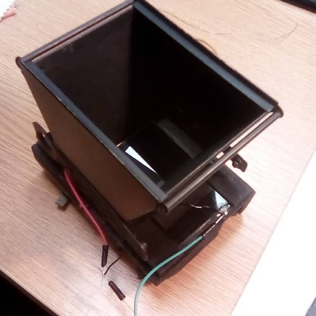
I wondered if there was any chance that I could fit the LCD element into the Brownie. As it turned out, the dimensions were almost perfectly suited to the space inside, and the Brownie was made out of easy-to-modify cardboard! The Robo-Brownie project was born.
It was at this point that I made an important discovery:
In order to effectively block light from passing through the LCD glass, a single element is insufficient. You actually need two stacked on top of one another. One one its own lets enough light through to accidentally fog the film, even when in “dark” mode. The problem is that, the way the polarisers were arranged on the rectangular glass meant that they would need to be mounted in a cross-shape, rather than flush. In other words, one element would need to be mounted at 90 degrees to the other. In that formation, the light-blocking capability was very strong indeed - strong enough to be used as a shutter. However, just to be sure, I left the original shutter intact and used it in T mode as an over-engineered lens cap!
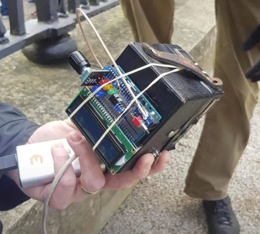
I modified the Brownie, fitted the glass, broke an element, replaced it, fitted a nice socket to the camera body, designed a control system with an Arduino, programmed a menu system, tested and tweaked and improved until I had a system that I thought would work.... and just in time. It was the Sunny 16 Photowalk in Oxford in February 2020 and I had a system that (although it looked like a bomb, like most of my projects) might just work. I re-spooled some 120 film onto a 620 spool and crossed my fingers.

Results
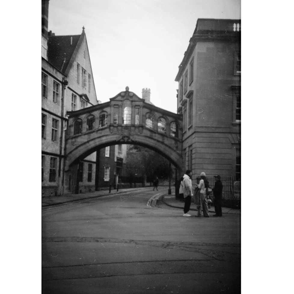
I was very excited to process the film and see what I had managed to capture. I will admit that I wasn’t expecting much but, when I saw the results I was blown away. This was a very old cardboard camera with a piece of welding goggles inside! I had images from bright and dark scenes, exposed roughly the way I’d “calculated” them (with a healthy amount of guess work!)

Interlude
You may remember what happened around March 2020? If not, congratulations! But it rather put a stop to my tinkering for a while. Everybody was forced home and the time and space I needed for electronics and cameras was very much at a premium in our tiny home full of 5 people!
Chroma
However, during that time, I was contacted by Steve Lloyd at Chroma Camera, who was interested in a collaborative project to make a similar shutter for a large-format camera. This immediately piqued my interest, but the tiny elements inside the welding glasses would not be large enough for a large-format lens. We had to go bigger.
Through searching, I found that there are full-face welding helmets that operate on the same principle. I tried several of these but they variously suffered from problems such as being the wrong shape or size, or having a colour cast, or a slow response, or too much light leakage. Eventually, I got hold of some “True-Color” 90x90mm lenses, which seemed to be the best compromise. The question was... could I make the control system more reliable and could we make it work at a larger scale?
How it works
The principle of an LCD element is the same as an old-fashioned digital watch, or calculator, or Tamagotchi! Polarised light is passed through a glass sandwich containing liquid crystals. These crystals are in a random orientation in the liquid but, when an electric field is applied to the glass, the crystals align with the field and create a controllable polarising filter. When the crystals are randomly oriented, light can pass. When they are aligned at right angles to the fixed polariser, light is blocked.
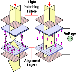
[LCD diagram courtesy of ptechguide.com]
Design Considerations
The principle is quite simple. In practice, I had read that DC voltages should not be used on LCD elements for too long, else the orientation of the crystals may be permanently altered, affecting switching times or transparency after a while. As my crystals needed to be “on” for most of the time (dark mode), this was a worry. I had to figure out how to make an AC drive mode that still blocked as much light as the DC mode.
I decided to use a system that alternately applied 5V and 0V to the contacts, then swapped over the 5V and 0V many times per second, rather than just keeping one at 0V and toggling the 5V one on and off. This is a sort of “bridge-tied-load” and allows the crystal to “see” an effective AC voltage at twice the amplitude of the other method without being damaged.
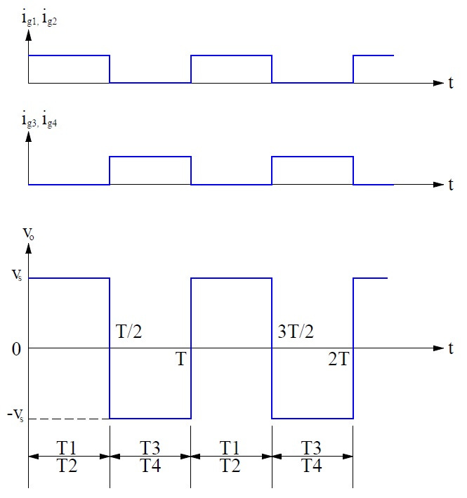
[BTL diagram courtesy of electricalbaba.com]
I wanted the timing to be really precise so I used logic gates rather than simply programming my Arduino to toggle two pins simultaneously. This is probably overkill and, if I’d put some effort into it, I could probably have figured out how to synchronously drive two pins at once! However, it did allow me to essentially use a free-running timer interrupt in the background, which constantly produces this square wave without tying up the microcontroller thread, and that I can gate with a separate signal when I want it on or off....
If the last paragraph meant nothing to you, don’t let it put you off! I just like to be thorough when documenting my projects :o)
So... I had a method. But did it work? In brief, yes!
It’s important to bear in mind that these glass elements are fragile. The glass is easily scratched and picks up fingerprints like nobody’s business; The electrical contacts are very delicate and, if you overheat them with a soldering iron, will just fall off (ask me how I know); The wires that come pre-fitted to them are extremely fine and susceptible to damage. So, be careful and/or keep spares if you try this yourself!
Chroma Results
Steve designed and 3D-printed an enclosure that would mount the LCD behind the lens, between the front standard and the bellows. He also designed a controller box and we worked out the firmware between us. We had a promising-looking demo!
But how did it work? I set up the camera in my garden, focused on a broom handle where I wanted to stand (still visible in the image, if you look between my legs!), used the self-timer function on my controller and ran into position for the photograph. Processing the sheet film in the bathroom immediately, I could hardly wait to see if it had worked... I think I’ll let you judge for yourselves!

Limitations
The way it is currently designed means that the shutter needs to be powered to be dark. Ideally, this would be reversed. In future, I may be able to find an LCD element that has its polariser fitter the opposite way round, which would allow it to be dark by default and clear when powered, which would save power. With that said, an LCD is basically a voltage-controlled device and barely consumes any current whatsoever... which is why they were so popular in digital watches and solar-powered calculators!
The other main limitation is that even when clear, the shutter blocks about two stops (3/4) of the light from the lens. For large-format photography, this is usually less of an issue because the shooting is already slow! In smaller formats, you can open the aperture, or use faster film, or a longer shutter speed, or some combination of the three. In practice, I didn’t find it to be too much of a limitation.
I would still recommend the use of a dark-slide (for large-format) or a lens cap (for smaller formats) because a very small amount of light can still pass through the glass when it is dark, but it really is extremely little, and it works perfectly well enough to take photos. You just wouldn’t want to rely on it for weeks on end with a piece of film behind the LCD... partly because your batteries may go flat and expose your film, and partly because over time very small leakage will build up and fog the image.
Off-the-shelf, the LCD elements are available in a limited variety of shapes and sizes, and some suffer from a tinted colour cast. All of these issues can be mitigated by careful component selection and, if you have the money, by ordering custom parts direct from the manufacturers.
Extensions
One interesting effect that I hadn’t expected when investigating this idea is that the LCD element can be driven with a PWM (Pulse-Width-Modulated) signal, which allows you to partially dim the glass rather than making it totally opaque. This has the same effect as a variable ND filter constructed from two rotating polarisers. I spent a little time trying to characterise this in the early days but found that the dimming amount was neither linear with pulse-width nor even monotonic (always goes up when pulse-width increases)! I definitely need to revisit this idea, though, because it opens up a lot of other photographic possibilities. A device like this is already commercially available for high-end movie cameras from Sony and another from Panasonic, so it’s definitely possible :)
I also managed to build a flash trigger and synchronise the shutter to the flash. This opens up a lot more opportunities for creative photography, as well as compensating somewhat for the loss of light through the shutter.
Applications
As well as a shutter for cameras, I can imagine applications in lighting (though LEDs are very fast to turn on and off, other lights that people may wish to use are not). I was once contacted by somebody who wanted to use one in their enlarger because the enlarger lamp takes a few seconds to reach full and stable brightness from cold. It could also be part of some fun toys or display pieces, or a type of Pepper’s Ghost illusion, with a bit of creativity. A similar system was once used in 3D glasses to synchronously show a different image to each eye, too.
I’m certain there are plenty of other applications, too. What sort of things can you think of?
p.s. I forget who took the top photo on the photo-walk! Sorry!